Introduction:
Without proper mission planing, a safe and practical mission cannot be flown. For example one must take into consideration drone battery life, weather conditions, elevations, areas where people are and flying would be illegal, and other obstacles such as radio towers and buildings that could affect flying. In this assignment mission planning is examined and practiced. Essentials before departure and in the field are explained. Then, the C-Astral made C³P mission planning software is explored, with basics such as the different terms, symbols, buttons, and windows with their specific functions covered. Next, the software is used to create two mission plans, one on the test field that automatically comes up when the software is opened, and another a field in Madison, WI. Finally the software is reviewed with summary of features and opinions.
Part 1: Mission Planning Essentials and Situational Awareness
Proper flight planning
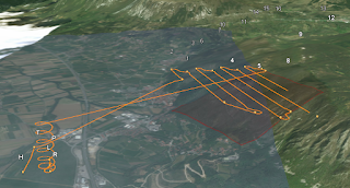
before departure is essential for later successful flight and mission goal completion. For preparation the study site needs to be known in as close to totality as possible. The cellular signal strength of the area needs to be known so that map data can be stored on the piloting computer or tablet ahead of time if there is not going to be signal in the field. It needs to be anticipated if crowds of people will be around the area flown because these are dangerous and illegal to fly over. Terrain, vegetation, and man made obstacles such as buildings and towers need to be known of so that correct flight paths and elevations can be chosen, and appropriately flat surfaces can be used to land on. These phenomena should be observed in person if possible, but geospatial data such as elevation contour (topographic) maps, aerial and satellite imagery, DEMs, and other information can and should be used as well. Many layers are available in the the C³P software, and three dimensional models of the flight plan can be viewed in the ESRI ArcGIS Earth software with the click of the 3D view under the map button menu (
Figure 1).
 |
| Figure 1 |
A good idea is to draw out multiple mission plans for the same area. This ensures another plan is available in the event of unforeseen obstacles.
Weather for the entire time of UAS operation should be attended to. Wind, air temperature, air pressure, visibility (drones must always be in line of sight), and rain can all affect flight performance. Wind direction should be considered also because fixed wing UAS needs to take off towards the direction wind is coming from for maximum lift. Also all batteries need to be charged in preparation.
Immediately before departure all equipment should be checked off of the checklist, and examined. A final weather check should also be done. The conditions and forcast may have changed since the last time checked, and if they have, flight may not be possible that day.
In the field planning must be done as well. Cellular network connection should first be confirmed. Field weather with wind speed, direction, temperature, and dew point must also be checked. This can be done with a pocket weather meter such as the Kestrel 3000 and a flag for direction. Vegetation and terrain must then be assessed for new or changed conditions, and to see if the flight plan will still work. Electromagnetic interference must be accounted for as well. Magnetic fields come with many metal objects, power lines, and power stations which can confuse the instruments on board the aircraft and the flight. These objects to be weary of can be underground (as with cabling or concrete rebar), on the surface (as with power stations), or in the air (as with power lines).
Other information for planning the flight needs to be found as well. The elevation of the launch site needs to be found so that an operator can be aware of where the aircraft is in relation to the launch site and landing site, and because some flights will require the information so that the drone can fly a consistent height above that elevation above that height for consistent spatial resolution. Standard units for flight should also be established between operators and planners so confusion will not arise. Metric, because it is the standard throughout the world, and is used in the Slovenian company C-Astral's software, is the obvious choice.
Finally, before flight, the missions previously planned should be reevaluated, and necessary changes made.
Part 2: Software Demonstration
 |
| Figure 2 |
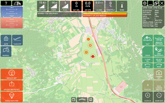
Figure 2 shows the entire main interface of the C³P software. Front and center is the map. Two maps can be toggled back and forth using the button in the top left corner shown in Figure 3. The maps default to the Google Terrain Map, and the Open Street Map. They can be changed, however, using the configuration button (Figure 4), the map tab in the window that opens, then the drop down menu. The best configuration is one map with imagery instead of digitized features, and one map that can show elevation.
 |
Figure 3
|
 |
| Figure 4 |
On the map are symbols that denote different areas used in the flight. There is an H that denotes the home area, the area where the control crew is stationed, a T that denotes the area of takeoff, an R, which denotes the area of Rally, the area where the UAV flies before its starts its final approach, and an L which denotes the landing area. All of these areas can be resized by hovering over the edge of the circle, clicking, and then dragging, to give the software more leeway in flight operation and designate a larger area for a certain function. These symbols can be seen in the center of
Figure 2. Click on this figure in order to see a larger version.
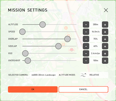
The mission settings window (Figure 5) can be used to adjust altitude, speed, sidelap and overlap, GSD, and overshoot. This window can be activated by the mission settings button shown on the right in Figure 2. Altitude can be set to a relative distance above ground level, or an absolute altitude above takeoff ground level (AGL). Speed must be set considering the speed at which the UAV will stall. The sidelap and overlap will adjust the distance between each flight path so that the percentage amount specified overlaps in the image with the next image, important for post processing. The GSD is the distance between each pixel on the ground, meaning that with a larger GSD a smaller spatial resolution will occur. Finally, overshoot is the distance outside the demarcated boxed area or street (corridor) area that the UAV can travel in order to turn around and enter on the next flight line.
 |
| Figure 5 |
The draw features are used for drawing a flight plan. They are all depicted in
Figure 6, which shows the open draw menu drawer. The measure tool can come in handy to find distance between area that need to be avoided and the flight path, as well as in appeasing other curiosities. The street points function can be used to draw along the center of a street, corridor, or power line, and later the width of the flight path can be extended to include more flight lines. The area points function lets one draw a unlimited sided polygon which covers the area desired to fly. The way points function lets one draw any path they would like to fly by the use of single points the UAV will fly through. All functions can be used by first opening the draw menu drawer with a click, then clicking on the appropriate tool, then clicking to make points on the map. Clicks with the street points tool should go down the middle of the line that one would like to cover, clicks with the area points tool define the corners of the polygon, and clicks on the map with the way points tool create points that the UAV will fly directly through.
 |
| Figure 6 |
The map menu button opens a drawer of map related features (Figure 6). One can jump to previous or new locations with the jump to location button, follow the UAV with the follow UAV button, show the trail of the flight, and even jump to a three dimensional view of the flight, which is opened in ESRI ArcGIS Earth if available (it is freeware), or Google Earth. This is an extraordinary feature for viewing the terrain interfering with the flight in planning.
Part 3: Working with the software
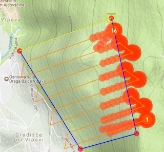
A few missions were planned for the Bramor test field that show what happens when altitudes settings are changed. Figure 7 shows a route for example which was made with the area points tool, whose flight is at an absolute elevation and is too low for the mountain area. The red points show the areas where the flight is too low and will hit the mountain. Figure 8 is the three dimensional view in ArcGIS Earth the right side of which shows this conflict.
 |
| Figure 7 |
 |
| Figure 8 |
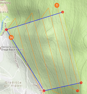
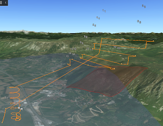
The flight path could be moved higher so that there would be no issue with intersection of the mountain, but a better way to mitigate this problem while also ensuring that that the spatial resolution of the area covered is consistent would be to make the elevation relative. This was changed in the mission settings window and the resulting flight is shown below in Figure 9 and 10. Also changed was the direction of the flight lines by dragging to resize the edge of the perimeter that runs the way the flight lines are desired. Flight lines should always go the long way, especially in this specific situation where more elevation climbing and descending would be necessary, even in overshoot, if the flight lines were perpendicular to the contour lines. Overlaps were set to the recommended setting for use with Pix4D.
 |
| Figure 9 |
 |
| Figure 10 |
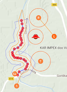
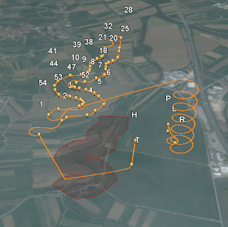
The next flight, which flies a corridor, is depicted in
Figures 11 and 12. The overlap again was set to an appropriate amount, the elevation set to relative for a consistent spatial resolution, and the width of the corridor changed to include a far reaching area. For efficiency, this plan put the takeoff area near the first point at the south area of the flight plan and the landing at the top. The rally area was moved to fit this design and be at the north of the field. The landing area was also strategically placed so that the UAV would not be landing towards, and possibly hitting, the home area. This placement would work only if the wind allowed the UAV to take off in the direction shown.
 |
| Figure 11 |
 |
| Figure 12 |
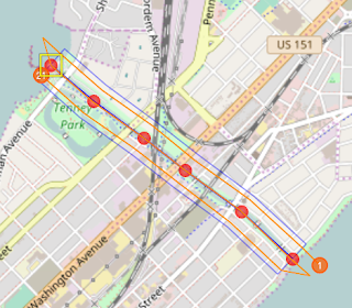
The last flight planned was one in Madison, WI, along the Yahara River connecting Lake Mendota to Lake Mendota. This plan was a corridor type plan. It again used relative elevation AGL for consistent spatial resolution. It is depicted in
Figures 13 and 14.
 |
| Figure 13 |
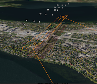 |
Figure 14
|
Part 4: Review of C³P:
At this point most functionality of this software has been covered and reviewed as well as mission planning essentials outside of the computer work. With the software's tools one can design different types of flights, and do it well informed because of the variety of geospatial data and three dimensional views that are offered.
The software struck me as fairly intuitive, and well featured, however there are a few features that I wish the software had. One is a drop-down menu of the different map views on the main interface screen. Having to go into the settings every time could be tedious and annoying in the field especially during flight if more information not available on a current map is desired. Another feature that could be included relating to this would be more map views to toggle through, and instead of a toggle button, the names of the different maps being displayed to tap or click on. This however may take up too much space on a tablet screen, and that is why the feature was not included. Another feature that could be included would be maps with elevations of buildings. This could aid the software in finding appropriate heights to fly at. At the current moment the software does not include the height of buildings and other man made structures so these have to be researched and included in planning so nothing goes awry. Towers and other structures besides buildings need to be considered alongside buildings.


