Introduction:
In last weeks project, a set of images captured by two UAS flights were brought into Pix4D and processed together to create a DSM, point cloud, and an orthomosaic. This project can be seen below under "Pix4D Image Processing. This week the same is being done, except that the two flights are being processed as separate projects. The projects are then both processed with Ground Control Points (GCPs), and are merged together later.
The fact that all of the data is processed with GCPs this week is big. The addition of GCPs means that the resulting orthomosaic and other data from the Pix4D process is much more spatially accurate (points in the imagery have much closer coordinates to their real world coordinates). GCP use starts with placing large markers on the ground. Large black and white, or black and yellow painted pieces of plywood were used for this specific project. These markers were placed spread out through the area being observed, and their locations in three dimensions recorded.
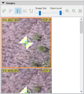
Figure 1 shows an example in imagery that was collected. The very center of this point was used to for collection of coordinates. These coordinates are then recorded to a list, and the details of where the marker was are recorded so that later in processing the marker can be identified in imagery. After enough markers are identified enough times (each can be seen in multiple images due to overlap), the Pix4D software can then predict where each specific marker is in more images, and it can predict where the other markers are in images. The system can then correct the geometry of the data being produced to reflect the GCPs and their locations in the imagery, creating much more spatially accurate data.
 |
| Figure 1 |
Methods:
 |
| Figure 2 |
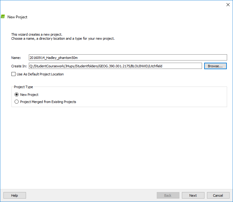
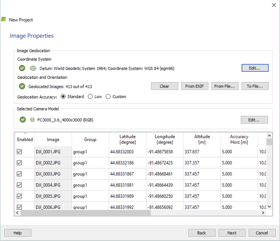
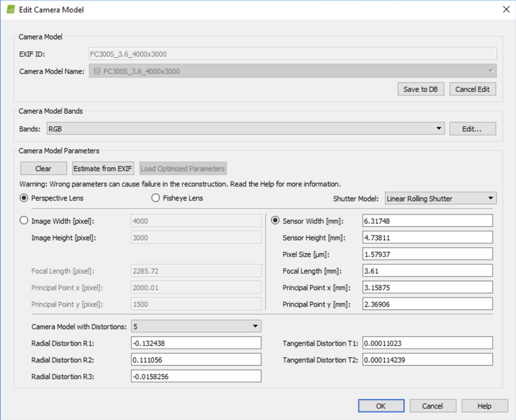
This week's methods were quite more involved than last weeks. In order to test out the project joining feature of the software, the two flights were processed separately instead of together, then joined. Each flight was processed with the same settings that were used last week (seen below under the title "Pix4D Image Processing") To recap, the photos of the parameters chosen are shown again below in Figures 2-4. Camera model settings had to be edited again because Pix4D does not recognize that the DJI Phantom 3 that was used has a rolling and not global shutter.
 |
| Figure 3 |
 |
| Figure 4 |
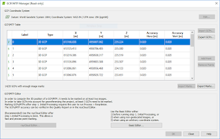
Figure 2 portrays a descriptive title similar to the titles given to the two projects processed. These titles were amended, however, to reflect their respected flight numbers. After these two projects were created, "Initial Processing" was run on each, the GCPs were added to each using the "Import GCPs" button and the text file supplied by the instructor (
Figure 6), and then they were combined. This process began with opening a new project in Pix4D, but instead of clicking on new project, clicking on "Project Merged From Existing Projects," the option highlighted in
Figure 5.
 |
| Figure 5 |
 |
| Figure 6 |
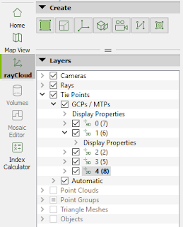
Each project file was then added to the subsequent list page, and "Initial Processing" was run again. Now, using the rayCloud view, GCPs were able to be located and pointed to in the imagery. After clicking on the specific GCP desired to be marked in the rayCLoud sidebar (
Figure 7), the specific point that was located was then clicked very accurately in the middle after using the zoom function to get as close as possible in the "Images" box in the lower right hand corner of the screen (
Figure 8). This was then done in a second image that was displayed below that image, after which "Apply", and then "Automatic Marking," were chosen in the above "Selection" box (
Figure 8). These selections then generated more images below the already pinpointed ones to pinpoint for more exact georeferencing. After doing these steps for most if not all of the GCPs, the data was reoptimized so that the imagery could be "tied down" (
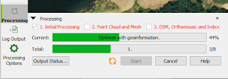
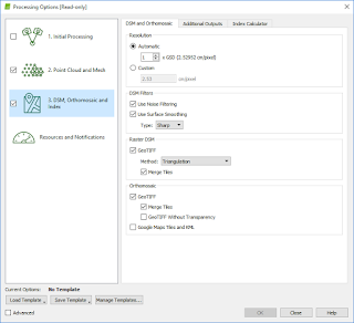
Figure 11) and the second two processing steps "Point Cloud and Mesh" and "DSM, Orthomosaic and Index" were run, making sure to uncheck "Initial Processing" and change the "Raster DSM GeoTIFF Method" to "Triangulation" in the DSM, "Orthomosaic and Index" tab of the "Processing Options" window, which gives better resulting images. These last steps involve areas of the software shown in
Figures 9-10.
 |
| Figure 7 |
 |
| Figure 8 |
 |
| Figure 9 |
 |
| Figure 10 |
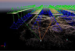 |
| Figure 11 |
These final steps allow the final DSM, three dimensional imagery (point cloud and triangle mesh), and the orthomosaic to be made. The DSM and orthomosaic can then be brought into ArcMap to create maps.
The addition of GCPs to the data increased the data quality by a lot. Having the GCPs allows Pix4D to create a real orthomosaic, which is geometrically corrected for the distortion introduced by differences in elevation. This creates a much more spatially correct image. The differences in spatial correctness can be seen below in
Figures 12-13.
Figure 12 shows the geolocation variance of the process after use of GCPs and
Figure 13 shows the same but without the use of GCPs.
 |
| Figure 12 |
 |
| Figure 13 |
Results:
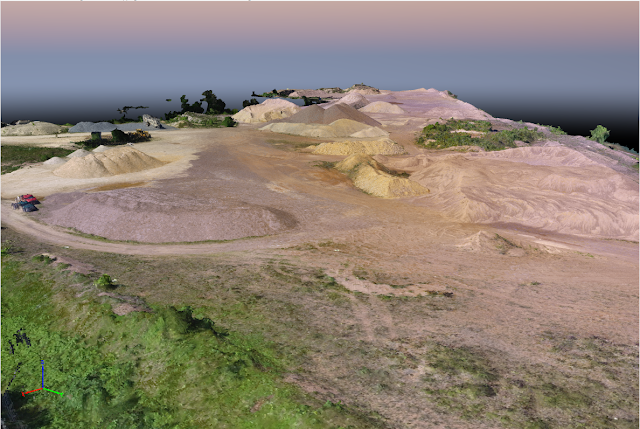
A view of the triangle mesh is shown in
Figure 14.
 |
| Figure 14 |
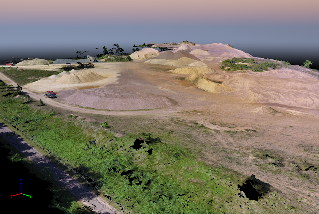
This image differs visually from the point cloud whose gaps are not filled in with triangles (
Figure 15).
 |
| Figure 15 |
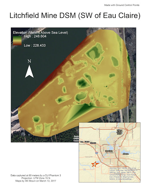
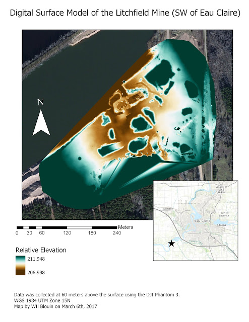
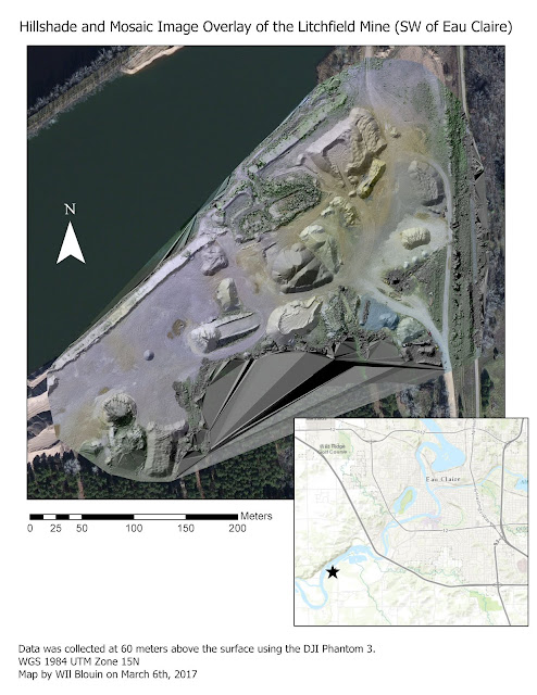
The resulting DSM from the data created is shown below in
Figure 16. The DSM created from last week's project is shown below that in
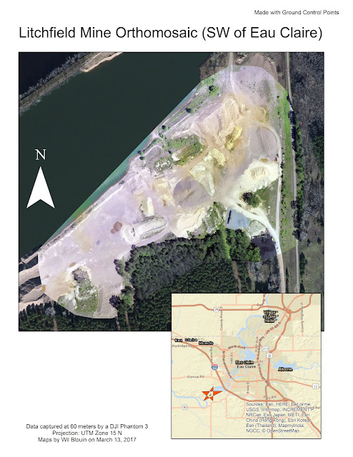
Figure 17. Next, the orthomosaic from this week is shown in
Figure 18, and then the orthomosaic from last week's project is shown below that in
Figure 19.
 |
| Figure 16 |
 |
| Figure 17 |
 |
| Figure 18 |
 |
| Figure 19 |
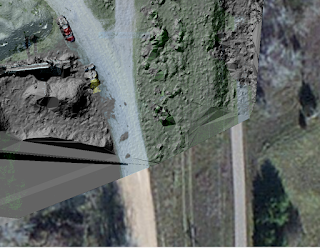
These can be subjected to scrutiny and be viewed zoomed in. When this happens, the real difference between the maps using GCPs and without the use of them can be seen. This is demonstrated below. In
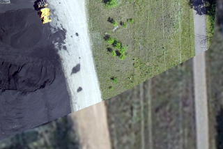
Figure 20, you can see a gap between where the side of the road is in the background (orthorectified) imagery is, and where the side of the road is in the Pix4D processed imagery is. This is the orthomosaic made without GCPs. In the next image,
Figure 21, there is far less of a gap, if there even is one. This is the magic of GCPs. The imagery is tied down at these points, and changes in elevation accounted for, to be able to orthorectify and geometrically correct the image for spatial accuracy.
 |
| Figure 20 |
 |
| Figure 21 |
Conclusion:
The addition of ground control points, although adding more time and energy to a project, is extremely important if highly spatially accurate information is wanted to be obtained. With the addition of GCPs, imagery can have spatial reference added to it that is far more accurate which means coordinates in the imagery mean the same points on the ground. The method used in this tutorial, with point coordinates of targets taken from the ground, is one way of doing this which works very well in Pix4D, but there are other ways as well. In software such as Erdas Imagine for example, one can use matching points in already highly accurate orthorectified images for the process (like the basemap that was added behind the imagery for comparison in Figure 20-21. For the Pix4D UAS data process however, this Xs on the ground method works very well and fits into the workflow, requiring a user not to have to use any other software.


No comments:
Post a Comment